
Refrigerant coil heat transfer
Computair’s WinCoil and WebCoil selection software support various types of coils, including hot water, cold water, steam, run-around, direct expansion/DX/evaporating, and condensing coils. Most of these coils utilize water (or water with additives such as glycol) and do not undergo any phase change. In other words, the water remains in either liquid or gas form as it passes through the coil, without transitioning between liquid and gas states.
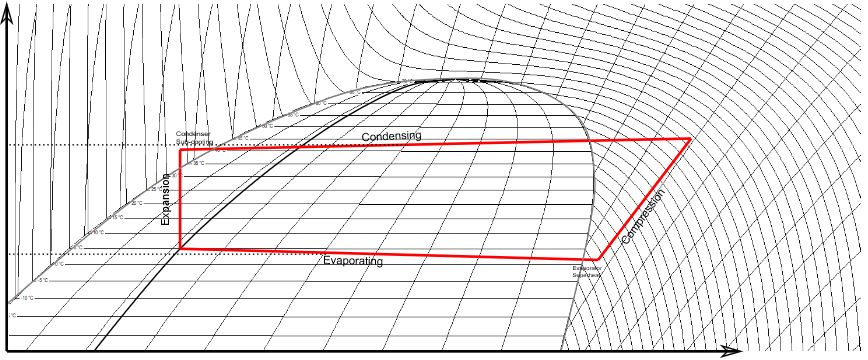
However, in evaporating coils and condensing coils, the circulating fluid (refrigerant) undergoes a phase change, either boiling from liquid to gas or condensing from gas to liquid. The associated release or absorption of latent heat constitutes a significant portion, if not the majority, of the heat exchange, as opposed to just a change in temperature. When Nigel Taffs developed Computair’s initial coil performance calculations in 1980, only a limited number of refrigerants were in use, and it was common practice to rely on simple graphs or tabulated data to determine heat transfer coefficients and changes in enthalpy. Since then, substantial changes have occurred, primarily due to government regulations governing the use of certain fluids historically employed as refrigerants. Computair’s coil performance calculations now incorporate the best available and proven mathematical models for refrigerant flow and heat transfer.
Modelling refrigerant flow
To determine heat transfer between refrigerant and tube, Computair’s coil software models the flow of the fluid as it either boils or condenses. Our models are not specific to a particular fluid but are based on implementations of the best theory available and use our database of thermodynamic and transport properties for each refrigerant. Thus, we can easily add new fluids as regulatory changes and industry trends demand.
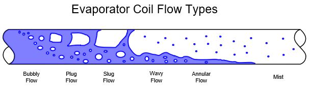
Modelling refrigerant flow through each coil circuit is complex, taking into account changes in vapour quality, flow regime and the geometry of the tube. For instance, as a refrigerant starts to boil it will be mostly liquid infused with bubbles of gas which will tend to be in the upper half of a horizontal coil tube. The refrigerant will continue to boil with more of the cross section occupied by gas until liquid exists only on the tube surface (annular flow). Eventually the refrigerant is almost entirely gas with entrained droplets (mist) before finally it has completely boiled and becomes superheated. Our coil software models all these kinds of flow in order to determine the heat transfer coefficient between the refrigerant and tube wall as well as the frictional pressure drop.
Supported refrigerants
Fluid | Composition (by mass for blends) | Class | GWP |
R14 | Tetrafluoromethane | PFC | 7390 |
R22 | Chlorodifluoromethane | HCFC | 1760 |
R23 | Trifluoromethane | HFC | 12400 |
R32 | Difluoromethane | HFC | 677 |
R134a | 1,1,1,2-Tetrafluoroethane | HFC | 1300 |
R170 | Ethane | HC | 0.437 |
R227ea | 1,1,1,2,3,3,3-Heptafluoropropane | HFC | 3350 |
R236fa | 1,1,1,3,3,3-Hexafluoropropane | HFC | 8060 |
R245fa | 1,1,1,3,3-Pentafluoropropane | HFC | 858 |
R290 | Propane | HC | 3.3 |
R404A | R125(44%)/R143a(4%)/R134a(52%) | HFC | 3922 |
R407A | R32(20%)/R125(40%)/R134a(40)%) | HFC | 2107 |
R407C | R32(23%)/R125(25%)/R134a (52%) | HFC | 1774 |
R407F | R32(30%)/R125(30%)/R134a(R40%) | HFC | 1825 |
R410A | R32(50%)/R125(50%) | HFC | 2088 |
R417A | R125(46.6%)/R134a(50%)/R600 (3.4%) | HFC | 2346 |
R442A | R32(31%)/R125(31%)/R134a(30%)/R152a(3%)/R600a(5%) | HFC | 1888 |
R448A | R32(26%)/R125(26%)/R134a(21%)/1234ze(7%)/1234yf(20%) | HFC/HFO | 1273 |
R449A | R32(24.3%)/R125(24.7%)/R134a(25.7%)/R1234yf(25.3%) | HFO | 1282 |
R452A | R32(67%)/R125(7%)/R1234yf(26%) | HFO | 676 |
R454A | R32(35%)/R1234yf(65%) | HFO | 239 |
R454B | R32(68.9%)/R1234yf(31.1%) | HFO | 467 |
R454C | R32(21.5%)/R1234yf(78.5%) | HFO | 148 |
R470A | R-744(10%)/R32(17%)/R125(19%)/R134a(7%)/R1234ze(E)(44%)/R227ea (3%) | HFO | 909 |
R470B | R-744(10%)/R32(11.5%)/R125(11.5%)/R134a(3%)/R1234ze(E)(57%)/R227ea (7%) | HFO | 717 |
R480A | R744(5%) / R1234ze(E)(86%) / R227ea(9%) | HFO | 302 |
R507A | R125(50%)/R143a(50%) | HFC | 3985 |
R508B | R23(46%)/R116(54%) | HFC | 13396 |
R513A | R1234yf(56%)/R134a(44%) | HFO | 573 |
R600a | Isobutane | HC | 3 |
R717 | Ammonia | - | 0 |
R723 | Ammonia(60%)/Dimethylether(40%) | - | 8 |
R728 | Nitrogen | - | 0 |
R744 | Carbon Dioxide | - | 1 |
R1234yf | 2,3,3,3-tetrafluoro-1-propene | HFO | 4 |
R1234ze(E) | trans-1,3,3,3-tetrafluoro-1-propene | HFO | 6 |
R1270 | Propene | HO | 1.8 |
Refrigerant properties
A few definitions
ENTHALPY
This is the heat of a refrigerant normally expressed as kJ/kg or BTU/lb. Normally a change in enthalpy at a constant pressure will cause a change in temperature. In the saturation zone there is no change or only a small change in temperature due to temperature glide and frictional pressure drop. But the proportion of gas to liquid (vapour quality) will change as the refrigerant boils or condensing, either absorbing or releasing latent heat as it does so.
VAPOUR QUALITY
This is the ratio of gas to liquid in the saturation zone. It is normally expressed as a percentage. It can be given as mass basis (kg of gas to kg of liquid) or mole basis (moles of gas to moles of liquid). The vapour quality at the inlet of the DX coil is determined from the condensing coil outlet condition.
CRITICAL POINT
The “critical point” of a refrigerant refers to the specific thermodynamic state at which the distinction between the liquid and gaseous phases of the substance becomes indistinguishable. At this critical point, the refrigerant experiences a unique set of conditions, including a critical temperature and critical pressure, beyond which any increase in temperature or pressure will not cause the substance to undergo a phase transition from liquid to gas or vice versa. Additionally, at the critical point, the density difference between the liquid and vapor phases disappears, resulting in a singular phase known as a supercritical fluid. The critical point is a crucial parameter in refrigerant applications, as it signifies the upper limits of pressure and temperature within which the refrigerant can exist as a distinct liquid and vapour, influencing system design and performance.
VISCOSITY
Viscosity, expressed as N·s/m2 or lb·s/ft2, refers to the internal resistance of the fluid to flow or deformation. It is a measure of the fluid’s thickness or resistance to shearing forces. In refrigeration systems, viscosity is a significant property as it influences the efficiency of fluid circulation, particularly in components like compressors and pumps. Refrigerants with higher viscosity may experience increased resistance to flow, potentially impacting the overall system performance. Conversely, low-viscosity refrigerants flow more easily, reducing pumping work and enhancing heat transfer efficiency. The viscosity of a refrigerant is often influenced by factors such as temperature and pressure, and it is an important consideration in designing and optimizing refrigeration systems.
DENSITY
The mass of fluid in a given volume normally expressed as kg/m3 or lb/ft3. As a fluid changes from liquid to gas its density changes enormously causing a changing in the speed the fluid flows through a DX coil on condensing coil. This is a factor affecting heat transfer and frictional pressure drop.
FRICTIONAL PRESSURE DROP
The frictional pressure drop through the condenser and evaporator coils is part of the work the compressor has to do. It also affects the temperature of the refrigerant.
ISOBARIC SPECIFIC HEAT CAPACITY
Isobaric specific heat capacity is the amount of heat energy required to raise the temperature of a unit mass of the substance by one degree Celsius (or one Kelvin) at constant pressure. It is expressed in units of energy per unit mass per degree temperature change (J/(kg·°K) or BTU/(lb·°R)). Isobaric specific heat capacity is a crucial thermodynamic property that characterizes the refrigerant’s response to changes in temperature at constant pressure. It plays a significant role in calculating the heat transfer throughout the refrigeration cycle.
SURFACE TENSION
Surface tension is the effect of the cohesive forces acting at the interface between the liquid and gas phases of the refrigerant. It is the property that causes the refrigerant’s surface to behave like a stretched elastic membrane. Surface tension is the result of molecular forces at the liquid-vapour interface, creating a tendency for the surface to minimize its area.
In refrigeration systems, surface tension plays a role in the processes of condensation and evaporation. For example, during condensation, the surface tension affects how the refrigerant forms and holds onto droplets. In evaporation, it influences the ability of the refrigerant to spread as a thin film on surfaces. An understanding of surface tension is crucial to the modelling heat transfer and phase change processes within refrigeration systems. It is an essential consideration in the design and performance of heat exchangers and other components in refrigeration applications.
TEMPERATURE GLIDE
This is a property of blended refrigerants. The components of the fluid may not evaporate on condense at the same rate causing a small change in temperature in the saturation zone when enthalpy changes. In DX coils this opposes the drop in temperature caused by the frictional pressure drop and may even overcome it. In condensing coils, it increases the temperature drop associated with frictional pressure drop.
States of fluid:
• Sub-cooled / liquid: This fluid state is characterised by incompressibility, surface tension, high density and viscosity
• Super-heated / liquid: This fluid state is characterised by compressibility, no surface tension, lower density and lower viscosity
• Saturated: The saturation zone is a range or pressure and enthalpy within which a fluid is composed of a mixture of liquid and gas. Changes to enthalpy can cause a change in the proportions of liquid and gas due to boiling or condensation
• Super-critical: Above the critical temperature and pressure a fluid exists in a state characterised by the density and viscosity of a liquid, but also the compressibility and no surface tension of a gas. It is typical for Carbon Dioxide (R744) based systems to take the fluid into this state.
Regulatory changes affecting refrigeration:
In the 1980’s a relationship between the depletion of the ozone layer and the release of chlorofluorocarbons (CFC’s) and hydrochlorofluorocarbons (HCFC’s) was discovered and international treaties were agreed which eliminated the use of these compounds. That meant that in the 1990’s CFC refrigerants such as R12 became obsoleten the 21st century HCFC refrigerants such as R22 started to be phased out. Other classes of compound including hydrofluorocarbons (HFC’s) were used as replacements.
In the 21st century further international action took place limiting the use of compounds with a high global warming potential (GWP). The GWP of a gas is defined as its contribution to global warming relative to carbon dioxide. For instance, R410A has a GWP of 2088 meaning that 1kg of R410A released into the atmosphere contributes as much to global warming as 2088kg of carbon dioxide. This has led to the progressive phase out of HFC’s.